Universal 71641 (Yellowed Example): Difference between revisions
No edit summary |
|||
| (3 intermediate revisions by the same user not shown) | |||
| Line 7: | Line 7: | ||
The '''Universal 71641''' is a six-outlet surge protector manufactured in 2004 and marketed for home and office electronic equipment. | The '''Universal 71641''' is a six-outlet surge protector manufactured in 2004 and marketed for home and office electronic equipment. | ||
The documented example exhibits significant enclosure yellowing and | The documented example exhibits significant enclosure yellowing and provides a useful example of long-term plastic aging in consumer electrical equipment. | ||
== Specifications == | == Specifications == | ||
| Line 23: | Line 23: | ||
** Approximately 1.31 in (3.3 cm) at the outlet section | ** Approximately 1.31 in (3.3 cm) at the outlet section | ||
** Approximately 1.63 in (4.1 cm) at the control section | ** Approximately 1.63 in (4.1 cm) at the control section | ||
* Voltage Rating: 125 VAC | * Voltage Rating: 125 VAC | ||
* Current Rating: 15 A | * Current Rating: 15 A | ||
| Line 36: | Line 34: | ||
* Flame Rating: VW-1 | * Flame Rating: VW-1 | ||
* UL File Number (Cord): E176194 | * UL File Number (Cord): E176194 | ||
* CSA File Number: LL109777 | * CSA File Number: LL109777 | ||
* Cord Manufacturer: Apollo | * Cord Manufacturer: Apollo | ||
* Weight: Approximately 1 lb 1.5 oz (496 g) | |||
== Physical Description == | |||
The Universal 71641 utilizes a low-profile beige plastic enclosure with six grounded outlets arranged in a single row and a raised control section near the power-cord entry point. | |||
A red rocker-style RESET/OFF power switch and a SURGE indicator are located in the control section. The switch is mounted perpendicular to the outlet row, a common arrangement on narrow single-row surge protectors of this period. | |||
The outlet nearest the rounded end of the enclosure is physically separated from the remaining receptacles and is specifically labeled "TRANSFORMER." The additional spacing provides clearance for oversized power adapters and wall-wart style transformers. | |||
The documented example exhibits substantial yellowing across most exposed surfaces. Areas adjacent to two outlet positions have retained noticeably lighter coloration, suggesting that two-prong devices may have remained plugged into the unit for extended periods. The protected areas appear to have been shielded from the environmental factors responsible for the surrounding discoloration. | |||
The cord-entry end incorporates an unused circular knockout molded into the enclosure. The feature appears intended to accommodate a resettable circuit breaker or similar component, although it is not populated on the documented example. Protection appears to be integrated into the switch and surge-suppression assembly. | |||
The attached power cord utilizes SJT construction with three 16 AWG conductors. Cord markings identify the manufacturer as Apollo and indicate CSA approval. | |||
== Weight == | |||
The documented example weighs approximately 1 lb 1.5 oz (496 g). | |||
[[File:surge_universal_71641_yellowed_weight_01.jpg|center|600px|Universal 71641 on a digital scale.]] | |||
== Mounting Provisions == | == Mounting Provisions == | ||
| Line 53: | Line 70: | ||
This provides greater installation flexibility than many previously documented surge protectors in the archive. | This provides greater installation flexibility than many previously documented surge protectors in the archive. | ||
== | == Product Gallery == | ||
<gallery mode="packed" heights="250"> | |||
File:surge_universal_71641_yellowed_main_01.jpg|Overall view of the yellowed Universal 71641. | |||
File:surge_universal_71641_yellowed_switch_01.jpg|Control section showing the power switch and surge indicator. | |||
File:surge_universal_71641_yellowed_middleoutlets_01.jpg|Outlet section showing differential yellowing. | |||
File:surge_universal_71641_yellowed_top_transformeroutlet_01.jpg|Dedicated transformer-spaced outlet. | |||
File:surge_universal_71641_yellowed_end_cordentry_01.jpg|Cord-entry end showing the control section and unused knockout. | |||
File:surge_universal_71641_yellowed_end_rounded_01.jpg|Rounded outlet-end profile. | |||
File:surge_universal_71641_yellowed_side_cordentryonright_01.jpg|Right-side profile view. | |||
File:surge_universal_71641_yellowed_side_cordentryonleft_01.jpg|Left-side profile view. | |||
File:surge_universal_71641_yellowed_bottom_overview_01.jpg|Underside view showing mounting provisions and product markings. | |||
File:surge_universal_71641_yellowed_bottom_ULsticker_01.jpg|UL certification hologram and listing information. | |||
File:surge_universal_71641_yellowed_bottom_middle_01.jpg|Underside specifications and ratings. | |||
File:surge_universal_71641_yellowed_bottom_cordentry_01.jpg|Mounting slots, date wheels, and cord-entry section. | |||
File:surge_universal_71641_yellowed_plug_detail_01.jpg|Grounding plug with molded approval markings. | |||
File:surge_universal_71641_yellowed_corddetail_01.jpg|Power cord specifications and approval markings. | |||
File:surge_universal_71641_yellowed_cable_detail_02.jpg|Additional power cord specifications and manufacturer markings. | |||
File:surge_universal_71641_yellowed_plug_01.jpg|Grounded attachment plug and power cord. | |||
</gallery> | |||
== Testing == | == Testing == | ||
| Line 86: | Line 104: | ||
When energized, the red SURGE indicator illuminated, indicating that surge-protection circuitry remained active. | When energized, the red SURGE indicator illuminated, indicating that surge-protection circuitry remained active. | ||
<gallery mode="packed" heights="250"> | <gallery mode="packed" heights="250"> | ||
| Line 93: | Line 110: | ||
File:surge_universal_71641_yellowed_testing_polaritygrounding_01.jpg|Outlet tester indicating correct wiring and grounding. | File:surge_universal_71641_yellowed_testing_polaritygrounding_01.jpg|Outlet tester indicating correct wiring and grounding. | ||
</gallery> | </gallery> | ||
== Condition Upon Acquisition == | |||
The documented example was acquired as part of a collection of surplus electrical equipment and exhibited significant yellowing, accumulated dirt, and cosmetic wear consistent with long-term use and storage. | |||
The unit was cleaned prior to detailed documentation and photography. | |||
[[File:surge_universal_71641_yellowed_beforecleaning_01.jpg|center|600px|71641 as acquired before cleaning.]] | |||
== Teardown == | == Teardown == | ||
| Line 98: | Line 124: | ||
The Universal 71641 enclosure is secured using multiple Phillips-head screws and can be opened non-destructively. | The Universal 71641 enclosure is secured using multiple Phillips-head screws and can be opened non-destructively. | ||
The upper housing contains molded outlet barriers, structural reinforcement ribs, | The upper housing contains molded outlet barriers, structural reinforcement ribs, outlet supports, and control-section structures. The lower housing contains stamped brass bus bars, outlet-contact assemblies, internal wiring, and the surge-suppression circuitry. | ||
The | Power distribution is accomplished using stamped brass bus bars running the length of the enclosure. The transformer-spaced outlet is integrated into the same bus-bar system as the remaining outlets. | ||
Further examination of the control-section circuit board revealed a larger and more sophisticated surge-suppression assembly than those documented in the earlier Universal 71632 and 71637 models. | |||
Visible components include: | |||
* Metal-oxide varistor (MOV) | |||
* Film capacitor | |||
* Power switch assembly | |||
* Surge-status indicator circuitry | |||
* Associated discrete protection components | |||
The | The suppression circuitry is concentrated on a dedicated printed circuit board mounted near the power-cord entry point. | ||
The | The larger circuit assembly suggests that Universal revised the internal surge-protection design between 1998 and 2004 while retaining the same basic bus-bar-based power-distribution architecture. | ||
Inspection of the documented example revealed dust accumulation and cosmetic contamination consistent with long-term use, but no obvious evidence of overheating, melting, or catastrophic electrical failure. | |||
<gallery mode="packed" heights="250"> | <gallery mode="packed" heights="250"> | ||
| Line 118: | Line 152: | ||
File:surge_universal_71641_yellowed_teardown_bottompanel_end_01.jpg|Transformer-outlet end showing bus-bar distribution. | File:surge_universal_71641_yellowed_teardown_bottompanel_end_01.jpg|Transformer-outlet end showing bus-bar distribution. | ||
File:surge_universal_71641_yellowed_teardown_bottompanel_middle_01.jpg|Center section showing bus bars and outlet contacts. | File:surge_universal_71641_yellowed_teardown_bottompanel_middle_01.jpg|Center section showing bus bars and outlet contacts. | ||
File:surge_universal_71641_yellowed_teardown_circuitboard_01.jpg|Surge-suppression circuit board and components. | |||
File:surge_universal_71641_yellowed_teardown_bottompanel_circuitcloseup_01.jpg|Close-up of the suppression circuitry. | |||
File:surge_universal_71641_yellowed_teardown_bottompanel_cordentry_01.jpg|Cord-entry end showing wiring and suppression circuitry. | |||
</gallery> | </gallery> | ||
== Product | == Product Family Context == | ||
The | The 71641 appears to represent a later evolution of Universal's surge-protector line. Compared with the 1998-era [[Universal 71632]] and [[Universal 71637]], the 71641 incorporates a dedicated transformer-spaced outlet, revised enclosure styling, and a larger surge-suppression assembly while retaining the same 330 V suppression rating. | ||
[[Category:Surge Protectors]] | |||
[[ | |||
Latest revision as of 19:31, 21 September 2026
Universal 71641 (Yellowed Example)

Overview
The Universal 71641 is a six-outlet surge protector manufactured in 2004 and marketed for home and office electronic equipment.
The documented example exhibits significant enclosure yellowing and provides a useful example of long-term plastic aging in consumer electrical equipment.
Specifications
- Manufacturer: Universal
- Model: 71641
- Manufacturing Date: May 23, 2004
- Outlets: 6 grounded outlets
- Transformer-spaced outlet: Yes
- Power Switch: Illuminated RESET/OFF rocker switch
- Surge Indicator: Yes
- Length: Approximately 10.5 in (26.7 cm)
- Width: Approximately 1.31 in (3.3 cm)
- Height:
- Approximately 1.31 in (3.3 cm) at the outlet section
- Approximately 1.63 in (4.1 cm) at the control section
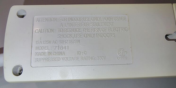
- Voltage Rating: 125 VAC
- Current Rating: 15 A
- Frequency: 60 Hz
- Maximum Load: 1875 W
- Suppressed Voltage Rating: 330 V
- Country of Manufacture: China
- Power Cord Length: Approximately 6 ft (1.8 m)
- Power Cord Type: SJT
- Conductors: 16 AWG × 3
- Flame Rating: VW-1
- UL File Number (Cord): E176194
- CSA File Number: LL109777
- Cord Manufacturer: Apollo
- Weight: Approximately 1 lb 1.5 oz (496 g)
Physical Description
The Universal 71641 utilizes a low-profile beige plastic enclosure with six grounded outlets arranged in a single row and a raised control section near the power-cord entry point.
A red rocker-style RESET/OFF power switch and a SURGE indicator are located in the control section. The switch is mounted perpendicular to the outlet row, a common arrangement on narrow single-row surge protectors of this period.
The outlet nearest the rounded end of the enclosure is physically separated from the remaining receptacles and is specifically labeled "TRANSFORMER." The additional spacing provides clearance for oversized power adapters and wall-wart style transformers.
The documented example exhibits substantial yellowing across most exposed surfaces. Areas adjacent to two outlet positions have retained noticeably lighter coloration, suggesting that two-prong devices may have remained plugged into the unit for extended periods. The protected areas appear to have been shielded from the environmental factors responsible for the surrounding discoloration.
The cord-entry end incorporates an unused circular knockout molded into the enclosure. The feature appears intended to accommodate a resettable circuit breaker or similar component, although it is not populated on the documented example. Protection appears to be integrated into the switch and surge-suppression assembly.
The attached power cord utilizes SJT construction with three 16 AWG conductors. Cord markings identify the manufacturer as Apollo and indicate CSA approval.
Weight
The documented example weighs approximately 1 lb 1.5 oz (496 g).

Mounting Provisions
The underside incorporates two keyhole-style mounting slots.
The mounting arrangement supports three practical installation orientations:
- Horizontal mounting
- Vertical mounting with the cord entry positioned upward
- Vertical mounting with the cord entry positioned downward
This provides greater installation flexibility than many previously documented surge protectors in the archive.
Product Gallery
-
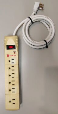 Overall view of the yellowed Universal 71641.
 -
 Control section showing the power switch and surge indicator.
 -
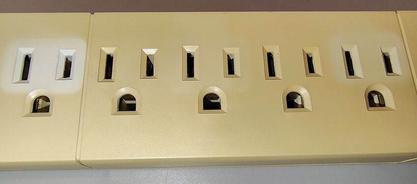 Outlet section showing differential yellowing.
 -
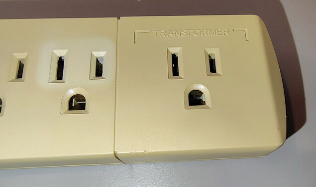 Dedicated transformer-spaced outlet.
 -
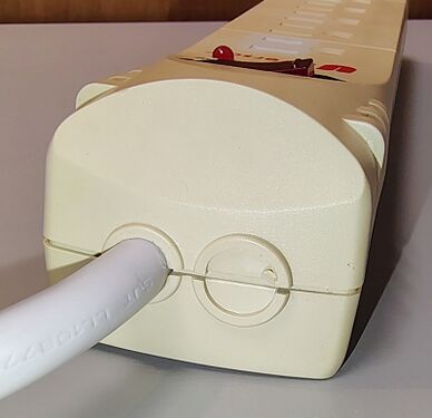 Cord-entry end showing the control section and unused knockout.
 -
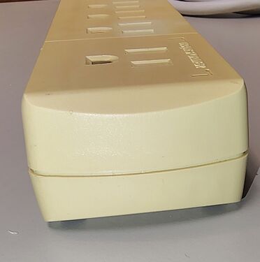 Rounded outlet-end profile.
 -
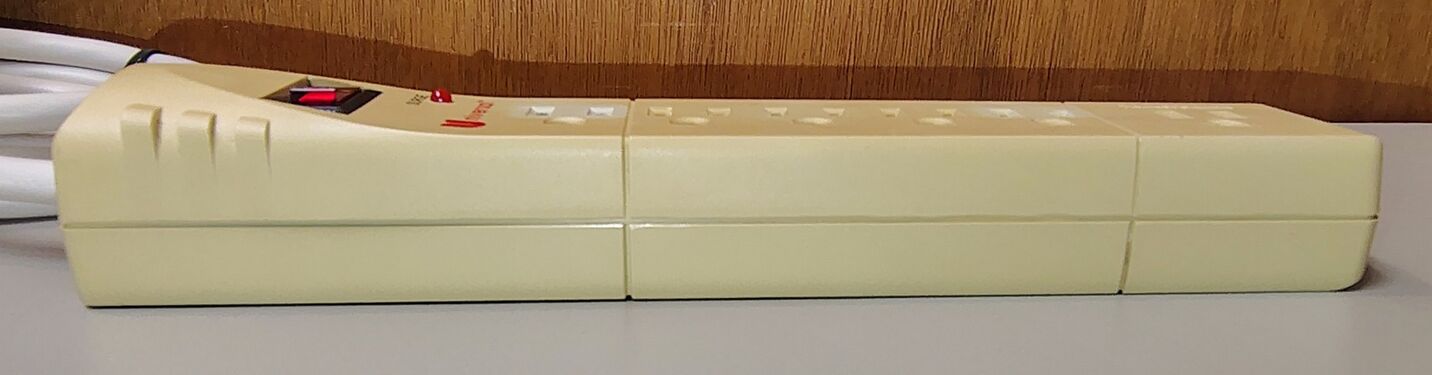 Right-side profile view.
 -
 Left-side profile view.
 -
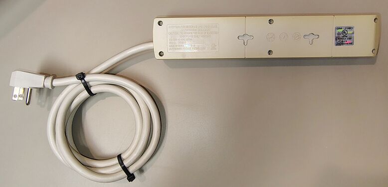 Underside view showing mounting provisions and product markings.
 -
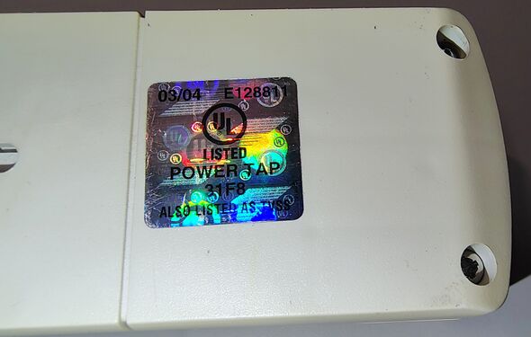 UL certification hologram and listing information.
 -
 Underside specifications and ratings.
 -
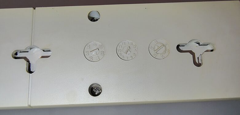
 Mounting slots, date wheels, and cord-entry section.
 -
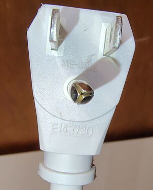 Grounding plug with molded approval markings.
 -
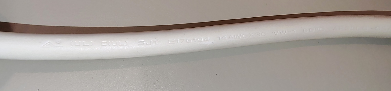 Power cord specifications and approval markings.
 -
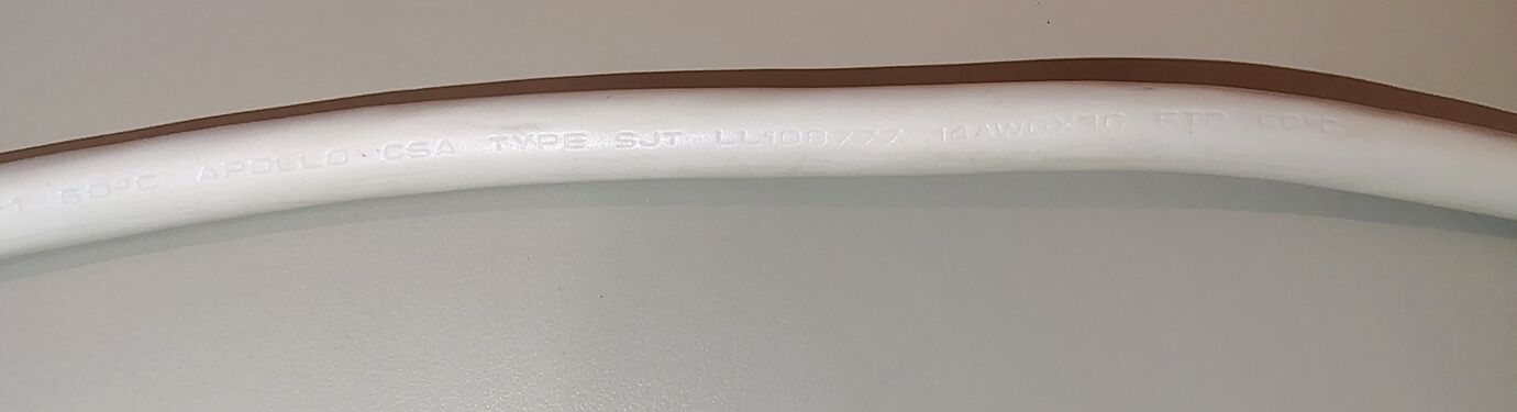 Additional power cord specifications and manufacturer markings.
 -
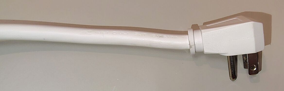 Grounded attachment plug and power cord.


Testing
The documented example was tested for basic electrical operation and wiring integrity.
Testing with a receptacle tester confirmed correct hot, neutral, and ground wiring. No open ground, open neutral, reversed polarity, or other wiring faults were detected.
The rocker switch successfully controlled power to all outlets.
When energized, the red SURGE indicator illuminated, indicating that surge-protection circuitry remained active.
-
 71641 connected to power with the rocker switch in the OFF position.
 -
 SURGE indicator illuminated during testing.
 -
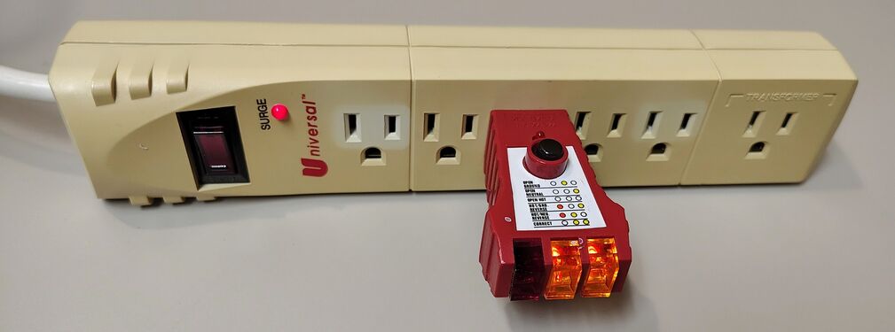 Outlet tester indicating correct wiring and grounding.


Condition Upon Acquisition
The documented example was acquired as part of a collection of surplus electrical equipment and exhibited significant yellowing, accumulated dirt, and cosmetic wear consistent with long-term use and storage.
The unit was cleaned prior to detailed documentation and photography.

Teardown
The Universal 71641 enclosure is secured using multiple Phillips-head screws and can be opened non-destructively.
The upper housing contains molded outlet barriers, structural reinforcement ribs, outlet supports, and control-section structures. The lower housing contains stamped brass bus bars, outlet-contact assemblies, internal wiring, and the surge-suppression circuitry.
Power distribution is accomplished using stamped brass bus bars running the length of the enclosure. The transformer-spaced outlet is integrated into the same bus-bar system as the remaining outlets.
Further examination of the control-section circuit board revealed a larger and more sophisticated surge-suppression assembly than those documented in the earlier Universal 71632 and 71637 models.
Visible components include:
- Metal-oxide varistor (MOV)
- Film capacitor
- Power switch assembly
- Surge-status indicator circuitry
- Associated discrete protection components
The suppression circuitry is concentrated on a dedicated printed circuit board mounted near the power-cord entry point.
The larger circuit assembly suggests that Universal revised the internal surge-protection design between 1998 and 2004 while retaining the same basic bus-bar-based power-distribution architecture.
Inspection of the documented example revealed dust accumulation and cosmetic contamination consistent with long-term use, but no obvious evidence of overheating, melting, or catastrophic electrical failure.
-
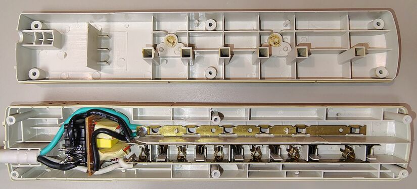 71641 opened following removal of the enclosure screws.
 -
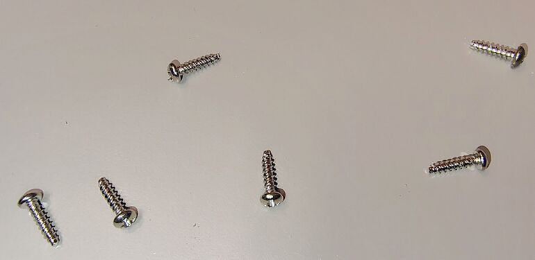 Enclosure screws removed during disassembly.
 -
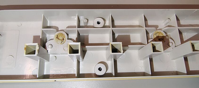 Upper housing outlet supports and structural details.
 -
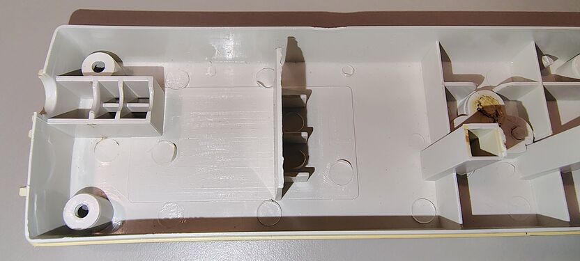 Control-section housing details.
 -
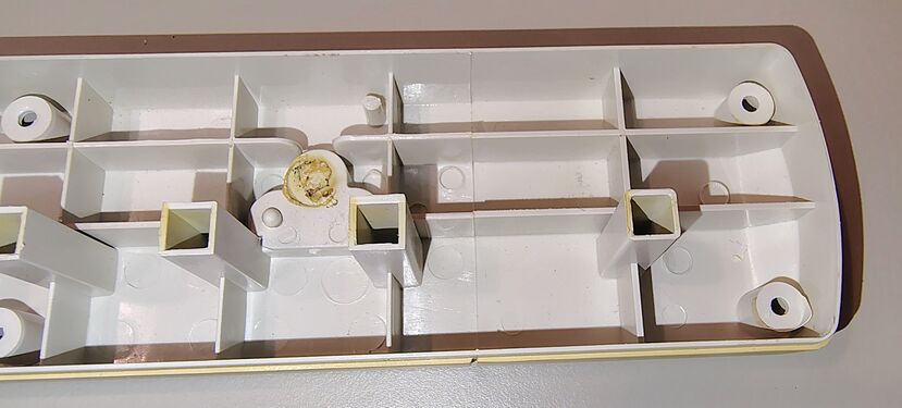 Upper housing details at the transformer-outlet end.
 -
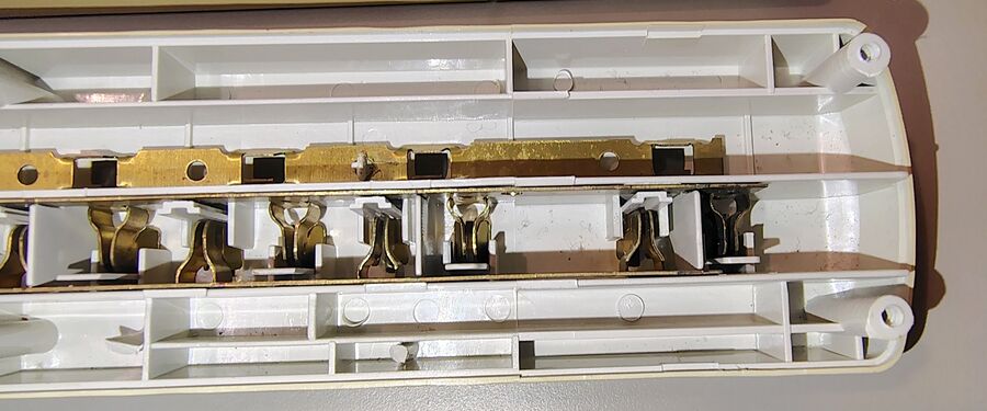 Transformer-outlet end showing bus-bar distribution.
 -
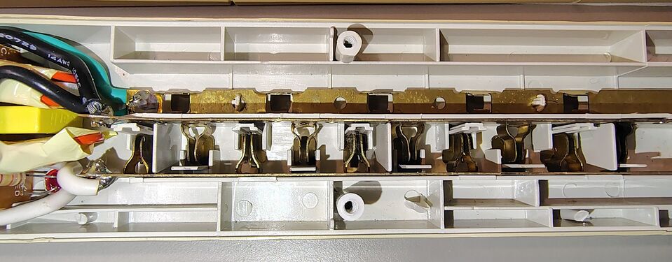 Center section showing bus bars and outlet contacts.
 -
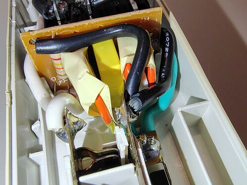 Surge-suppression circuit board and components.
 -
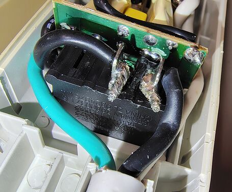 Close-up of the suppression circuitry.
 -
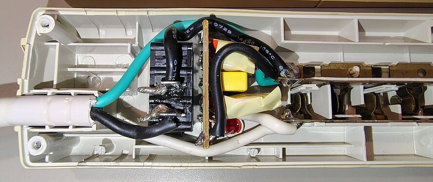 Cord-entry end showing wiring and suppression circuitry.


Product Family Context
The 71641 appears to represent a later evolution of Universal's surge-protector line. Compared with the 1998-era Universal 71632 and Universal 71637, the 71641 incorporates a dedicated transformer-spaced outlet, revised enclosure styling, and a larger surge-suppression assembly while retaining the same 330 V suppression rating.