Universal 71632: Difference between revisions
No edit summary |
No edit summary |
||
| (10 intermediate revisions by the same user not shown) | |||
| Line 7: | Line 7: | ||
The '''Universal 71632''' is a six-outlet surge protector manufactured in 1998 and marketed for home and office electronic equipment. | The '''Universal 71632''' is a six-outlet surge protector manufactured in 1998 and marketed for home and office electronic equipment. | ||
The model appears to represent a simpler companion product to the [[Universal 71637]], retaining | The model appears to represent a simpler companion product to the [[Universal 71637]], retaining core surge-protection functionality while omitting the integrated telephone-line protection found on the larger model. | ||
Although less feature-rich than the Universal 71637, the 71632 retains Universal's "Power Shut Down Protection" feature and appears to share much of the same underlying surge-suppression architecture. | |||
== Specifications == | == Specifications == | ||
| Line 28: | Line 30: | ||
** Approximately 1.38 in (3.5 cm) at the control section | ** Approximately 1.38 in (3.5 cm) at the control section | ||
* Height: Approximately 1.25 in (3.2 cm) | * Height: Approximately 1.25 in (3.2 cm) | ||
* Weight: Approximately 15.3 oz (434 g) | |||
* Power Cord Length: Approximately 6 ft (1.8 m) | |||
* Power Cord Type: SJT | |||
* Conductors: 16 AWG × 3 | |||
* Cord Temperature Rating: 75°C | |||
* Cord Manufacturer: Bon-Eagle | |||
* CSA File Number: LL95737 | |||
* Country of Manufacture: China | * Country of Manufacture: China | ||
== Physical Description == | == Physical Description == | ||
The Universal 71632 utilizes a slim off-white plastic enclosure with six grounded outlets arranged in a single row. | The Universal 71632 utilizes a slim off-white plastic enclosure with six grounded outlets arranged in a single row. | ||
A rocker-style RESET/OFF switch and protection-status indicator are located in the raised control section near the power-cord entry point. | A red rocker-style RESET/OFF switch and protection-status indicator are located in the raised control section near the power-cord entry point. The rocker switch is mounted perpendicular to the outlet row, a common arrangement on narrow single-row surge protectors of this period. | ||
Despite omitting the telephone-line protection found on the Universal 71637, the 71632 retains the same "Power Shut Down Protection" feature. | |||
According to the product labeling, the unit will cease conducting power after its surge-suppression components have reached the end of their protective life. This design prevents continued operation without surge protection. | |||
The attached power cord utilizes SJT construction with three 16 AWG conductors and a 75°C temperature rating. The grounded attachment plug carries CSA certification markings and is permanently attached through a molded strain relief. | |||
== Mounting Provisions == | == Mounting Provisions == | ||
The underside | The underside incorporates two keyhole-style mounting slots. | ||
The slot arrangement supports mounting in either horizontal or vertical orientations, allowing the unit to be installed on a wall, cabinet, or other flat surface. | The slot arrangement supports mounting in either horizontal or vertical orientations, allowing the unit to be installed on a wall, cabinet, or other flat surface. | ||
== Product Gallery == | == Product Gallery == | ||
| Line 87: | Line 72: | ||
File:surge_Universal_71632_1998_bottom_cableentryend_01.jpg|Power Shut Down Protection label and mounting provisions. | File:surge_Universal_71632_1998_bottom_cableentryend_01.jpg|Power Shut Down Protection label and mounting provisions. | ||
File:surge_Universal_71632_1998_bottom_middle_01.jpg|Underside specifications and ratings. | File:surge_Universal_71632_1998_bottom_middle_01.jpg|Underside specifications and ratings. | ||
File:surge_Universal_71632_1998_plug_close_01.jpg|Grounding plug with certification markings. | |||
File:surge_Universal_71632_1998_cable_detail_01.jpg|Power cord specifications and manufacturer markings. | |||
File:surge_Universal_71632_1998_cable_close_01.jpg|Additional cord specifications and markings. | |||
File:surge_Universal_71632_1998_plug_cable_01.jpg|Grounded plug and attached power cord. | |||
</gallery> | |||
== Testing == | |||
The documented example was tested for basic electrical operation and wiring integrity. | |||
Testing with a receptacle tester confirmed correct hot, neutral, and ground wiring. No open ground, open neutral, reversed polarity, or other wiring faults were detected. | |||
The rocker switch successfully controlled power to all outlets. | |||
When energized, the rocker switch illuminated and the protection-status indicator remained lit. The illuminated switch exhibited visible flicker during operation. Unlike the behavior observed on the Tripp Lite SPIKE BAR SK6-6, the illumination in the Universal 71632 appeared to move along the length of the rocker switch rather than switching completely on and off. | |||
A video demonstrating the flicker behavior is available: | |||
[https://youtu.be/NFu8fP-OsU8 Demonstration video] | |||
<gallery mode="packed" heights="250"> | |||
File:surge_Universal_71632_1998_testing_pluggedin_nopowerlight_01.jpg|71632 connected to power with the rocker switch in the OFF position. | |||
File:surge_Universal_71632_1998_testing_poweronlightlit_01.jpg|71632 connected to power with the rocker switch in the ON position. | |||
File:surge_Universal_71632_1998_testing_polaritygrounding_01.jpg|Outlet tester indicating correct wiring and grounding. | |||
</gallery> | |||
== Weight == | |||
The documented example weighs approximately 15.3 oz (434 g). | |||
[[File:surge_Universal_71632_1998_weight_01.jpg|center|600px|Universal 71632 on a digital scale.]] | |||
== Condition Upon Acquisition == | |||
The documented example was acquired as part of a collection of surplus electrical equipment and exhibited accumulated dust, dirt, and cosmetic wear consistent with long-term use and storage. | |||
The unit was cleaned prior to detailed documentation and photography. | |||
[[File:surge_Universal_71632_1998_beforecleaning_01.jpg|center|600px|Universal 71632 as acquired before cleaning.]] | |||
== Condition Notes == | |||
The documented example exhibits damage to one of the internal screw-post assemblies near the power-cord entry point. As a result, the upper and lower housing halves no longer clamp tightly together in that corner, resulting in a visible gap in the enclosure. | |||
The damage appears mechanical rather than electrical in nature. One possible explanation is that the surge protector was mounted to a fixed surface and the power cord was subjected to a sudden pulling force, such as a person tripping over the cord. | |||
No evidence of overheating, arcing, melting, or catastrophic electrical failure was observed in the damaged area. | |||
== Teardown == | |||
The Universal 71632 enclosure is secured using six Phillips-head screws and can be opened non-destructively. | |||
One of the internal screw-post assemblies near the power-cord entry point was found to be damaged prior to documentation. The damage prevented complete removal of one enclosure screw, leaving it retained within the broken plastic post during disassembly. | |||
The upper housing contains molded outlet barriers, mounting-slot structures, and screw bosses that position and secure the outlet-contact assemblies. | |||
The lower housing contains stamped brass bus bars, outlet-contact assemblies, internal wiring, and a compact surge-suppression circuit located within the raised control section. | |||
Unlike the Universal 71637, the 71632 omits telephone-line protection circuitry and associated RJ11 connectors. The remainder of the construction is broadly similar, utilizing stamped brass conductors and a compact surge-suppression assembly. | |||
Further examination of the control-section circuit board revealed: | |||
* Metal-oxide varistor (MOV) | |||
* Thermal protection device | |||
* Capacitor | |||
* Power indicator circuitry | |||
* Rocker switch assembly | |||
The surge-suppression circuitry is concentrated on a small printed circuit board mounted near the power-cord entry point. The board is mechanically integrated into the outlet bus structure and could not be removed easily without desoldering the bus bars. | |||
To avoid unnecessary risk to the documented example, the circuit board was not removed from the enclosure. | |||
The layout appears consistent with the "Power Shut Down Protection" feature described on the product label. A thermal protection device is mounted in close proximity to the surge-suppression components, allowing the unit to disconnect power after the suppression network reaches the end of its useful life. | |||
One corner of the enclosure exhibits visible separation between the upper and lower housing halves. This condition is directly related to the damaged screw-post assembly found during disassembly. | |||
Inspection of the interior revealed light dust accumulation and minor contamination but no obvious evidence of overheating, melted components, or catastrophic electrical failure. | |||
<gallery mode="packed" heights="250"> | |||
File:surge_Universal_71632_1998_teardown_open_01.jpg|71632 opened following removal of the enclosure screws. | |||
File:surge_Universal_71632_1998_teardown_fiveofsixscrews_01.jpg|Five of six enclosure screws removed during disassembly. | |||
File:surge_Universal_71632_1998_teardown_broken_internal_plastic_01.jpg|Broken internal screw-post assembly. | |||
File:surge_Universal_71632_1998_teardown_toppanel_outlets_01.jpg|Upper housing outlet supports and mounting structures. | |||
File:surge_Universal_71632_1998_teardown_bottompanel_outlets_01.jpg|Outlet-end bus bars and outlet-contact assemblies. | |||
File:surge_Universal_71632_1998_teardown_toppanel_cordentry_01.jpg|Control-section housing details. | |||
File:surge_Universal_71632_1998_teardown_circuitboard_side_01.jpg|Side view of the surge-suppression circuit board. | |||
File:surge_Universal_71632_1998_teardown_bottompanel_cordentry_01.jpg|Cord-entry end showing wiring and bus-bar connections. | |||
File:surge_Universal_71632_1998_teardown_circuitboard_cordentry_01.jpg|Surge-suppression circuit board and cord-entry wiring. | |||
File:surge_Universal_71632_1998_teardown_circuitboard_side_02.jpg|Alternate side view of the surge-suppression circuit board. | |||
File:surge_Universal_71632_1998_separation_frombrokeninternalplastic_01.jpg|Housing separation caused by the broken internal screw post. | |||
</gallery> | </gallery> | ||
[[Category:Surge Protectors]] | |||
Latest revision as of 14:15, 20 September 2026
Universal 71632

Overview
The Universal 71632 is a six-outlet surge protector manufactured in 1998 and marketed for home and office electronic equipment.
The model appears to represent a simpler companion product to the Universal 71637, retaining core surge-protection functionality while omitting the integrated telephone-line protection found on the larger model.
Although less feature-rich than the Universal 71637, the 71632 retains Universal's "Power Shut Down Protection" feature and appears to share much of the same underlying surge-suppression architecture.
Specifications
- Manufacturer: Universal
- Model: 71632
- Manufacturing Year: 1998
- Voltage Rating: 125 VAC
- Current Rating: 15 A
- Frequency: 60 Hz
- Maximum Load: 1875 W
- UL 1449 Suppressed Voltage Rating: 330 V
- Protection Modes:
- Line-to-Neutral (L-N)
- Line-to-Ground (L-G)
- Neutral-to-Ground (N-G)
- Length: Approximately 10.25 in (26.0 cm)
- Width:
- Approximately 1.50 in (3.8 cm) at the outlet section
- Approximately 1.38 in (3.5 cm) at the control section
- Height: Approximately 1.25 in (3.2 cm)
- Weight: Approximately 15.3 oz (434 g)
- Power Cord Length: Approximately 6 ft (1.8 m)
- Power Cord Type: SJT
- Conductors: 16 AWG × 3
- Cord Temperature Rating: 75°C
- Cord Manufacturer: Bon-Eagle
- CSA File Number: LL95737
- Country of Manufacture: China
Physical Description
The Universal 71632 utilizes a slim off-white plastic enclosure with six grounded outlets arranged in a single row.
A red rocker-style RESET/OFF switch and protection-status indicator are located in the raised control section near the power-cord entry point. The rocker switch is mounted perpendicular to the outlet row, a common arrangement on narrow single-row surge protectors of this period.
Despite omitting the telephone-line protection found on the Universal 71637, the 71632 retains the same "Power Shut Down Protection" feature.
According to the product labeling, the unit will cease conducting power after its surge-suppression components have reached the end of their protective life. This design prevents continued operation without surge protection.
The attached power cord utilizes SJT construction with three 16 AWG conductors and a 75°C temperature rating. The grounded attachment plug carries CSA certification markings and is permanently attached through a molded strain relief.
Mounting Provisions
The underside incorporates two keyhole-style mounting slots.
The slot arrangement supports mounting in either horizontal or vertical orientations, allowing the unit to be installed on a wall, cabinet, or other flat surface.
Product Gallery
-
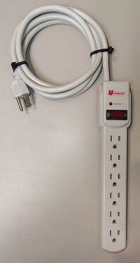 Overall view of the Universal 71632.
 -
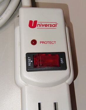 Universal branding, protection indicator, and power switch.
 -
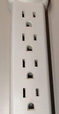 Four of six grounded AC outlets.
 -
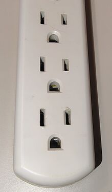 Outlet-end detail.
 -
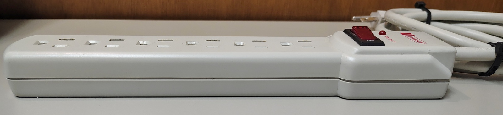 Right-side profile view.
 -
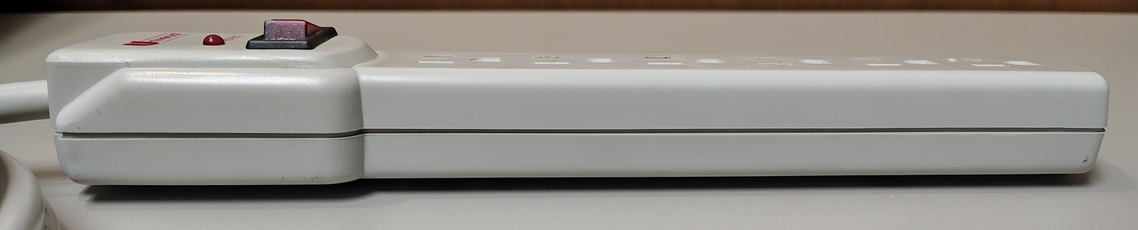 Left-side profile view.
 -
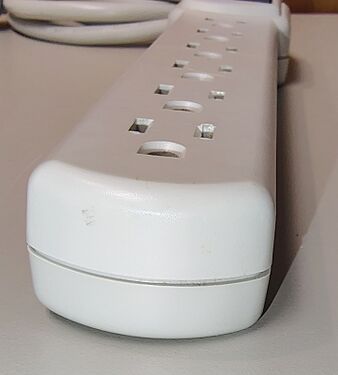 Rounded outlet-end profile.
 -
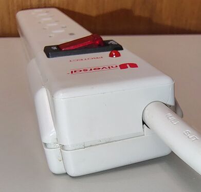 Cord-entry end showing the control section.
 -
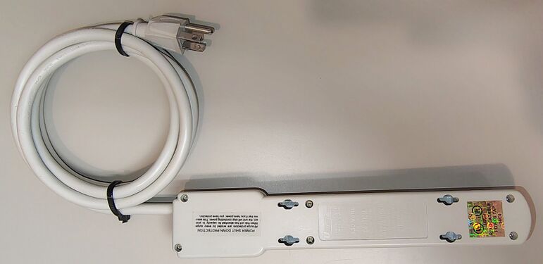 Underside view showing mounting provisions and product markings.
 -
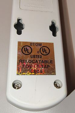 UL certification label and mounting-slot detail.
 -
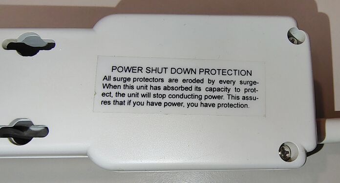 Power Shut Down Protection label and mounting provisions.
 -
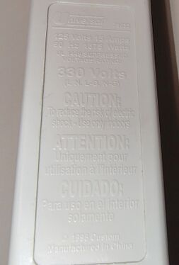 Underside specifications and ratings.
 -
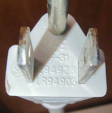 Grounding plug with certification markings.
 -
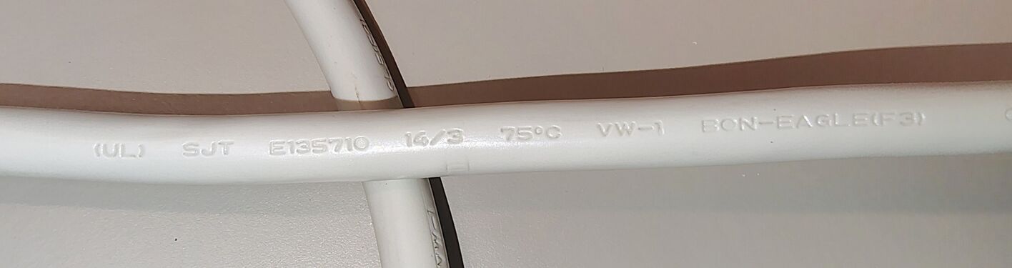 Power cord specifications and manufacturer markings.
 -
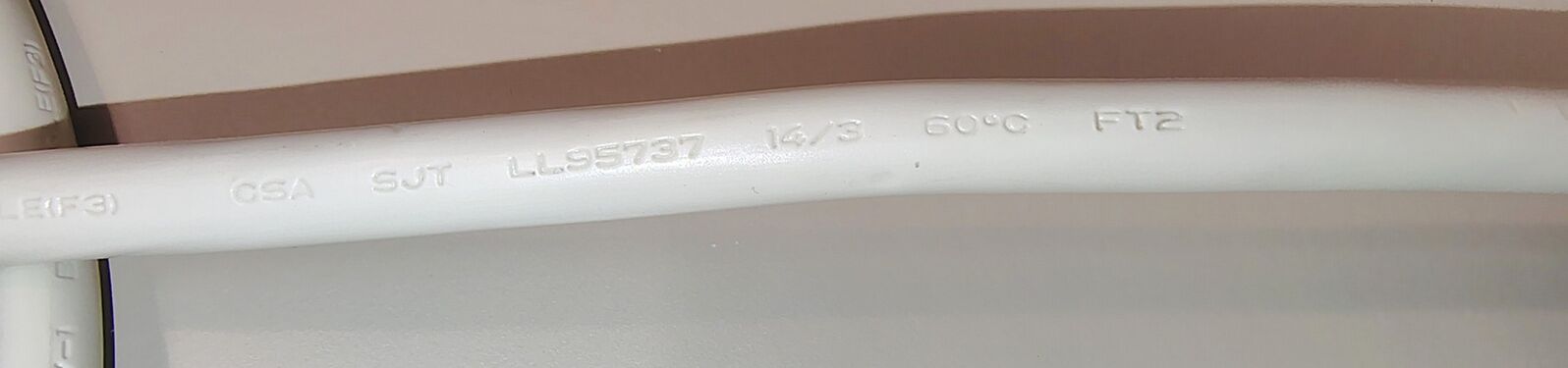 Additional cord specifications and markings.
 -
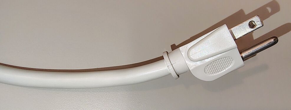 Grounded plug and attached power cord.


Testing
The documented example was tested for basic electrical operation and wiring integrity.
Testing with a receptacle tester confirmed correct hot, neutral, and ground wiring. No open ground, open neutral, reversed polarity, or other wiring faults were detected.
The rocker switch successfully controlled power to all outlets.
When energized, the rocker switch illuminated and the protection-status indicator remained lit. The illuminated switch exhibited visible flicker during operation. Unlike the behavior observed on the Tripp Lite SPIKE BAR SK6-6, the illumination in the Universal 71632 appeared to move along the length of the rocker switch rather than switching completely on and off.
A video demonstrating the flicker behavior is available:
-
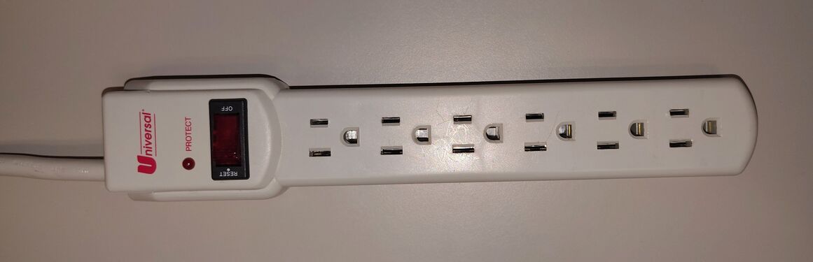 71632 connected to power with the rocker switch in the OFF position.
 -
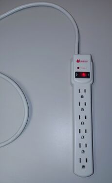 71632 connected to power with the rocker switch in the ON position.
 -
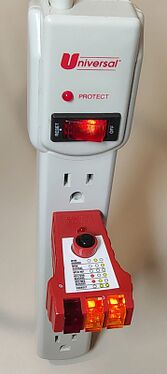 Outlet tester indicating correct wiring and grounding.


Weight
The documented example weighs approximately 15.3 oz (434 g).

Condition Upon Acquisition
The documented example was acquired as part of a collection of surplus electrical equipment and exhibited accumulated dust, dirt, and cosmetic wear consistent with long-term use and storage.
The unit was cleaned prior to detailed documentation and photography.

Condition Notes
The documented example exhibits damage to one of the internal screw-post assemblies near the power-cord entry point. As a result, the upper and lower housing halves no longer clamp tightly together in that corner, resulting in a visible gap in the enclosure.
The damage appears mechanical rather than electrical in nature. One possible explanation is that the surge protector was mounted to a fixed surface and the power cord was subjected to a sudden pulling force, such as a person tripping over the cord.
No evidence of overheating, arcing, melting, or catastrophic electrical failure was observed in the damaged area.
Teardown
The Universal 71632 enclosure is secured using six Phillips-head screws and can be opened non-destructively.
One of the internal screw-post assemblies near the power-cord entry point was found to be damaged prior to documentation. The damage prevented complete removal of one enclosure screw, leaving it retained within the broken plastic post during disassembly.
The upper housing contains molded outlet barriers, mounting-slot structures, and screw bosses that position and secure the outlet-contact assemblies.
The lower housing contains stamped brass bus bars, outlet-contact assemblies, internal wiring, and a compact surge-suppression circuit located within the raised control section.
Unlike the Universal 71637, the 71632 omits telephone-line protection circuitry and associated RJ11 connectors. The remainder of the construction is broadly similar, utilizing stamped brass conductors and a compact surge-suppression assembly.
Further examination of the control-section circuit board revealed:
- Metal-oxide varistor (MOV)
- Thermal protection device
- Capacitor
- Power indicator circuitry
- Rocker switch assembly
The surge-suppression circuitry is concentrated on a small printed circuit board mounted near the power-cord entry point. The board is mechanically integrated into the outlet bus structure and could not be removed easily without desoldering the bus bars.
To avoid unnecessary risk to the documented example, the circuit board was not removed from the enclosure.
The layout appears consistent with the "Power Shut Down Protection" feature described on the product label. A thermal protection device is mounted in close proximity to the surge-suppression components, allowing the unit to disconnect power after the suppression network reaches the end of its useful life.
One corner of the enclosure exhibits visible separation between the upper and lower housing halves. This condition is directly related to the damaged screw-post assembly found during disassembly.
Inspection of the interior revealed light dust accumulation and minor contamination but no obvious evidence of overheating, melted components, or catastrophic electrical failure.
-
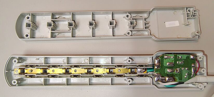 71632 opened following removal of the enclosure screws.
 -
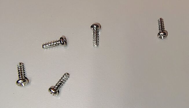 Five of six enclosure screws removed during disassembly.
 -
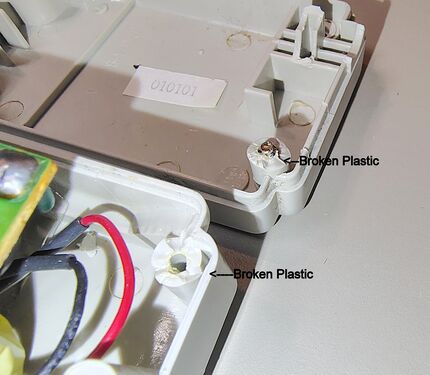 Broken internal screw-post assembly.
 -
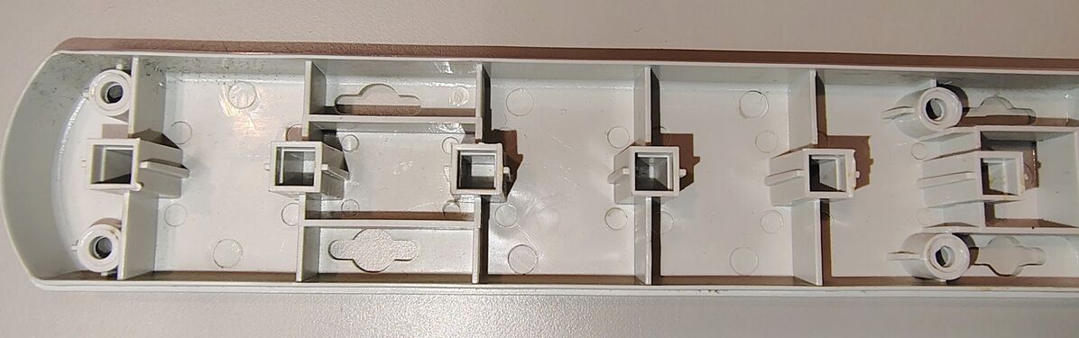 Upper housing outlet supports and mounting structures.
 -
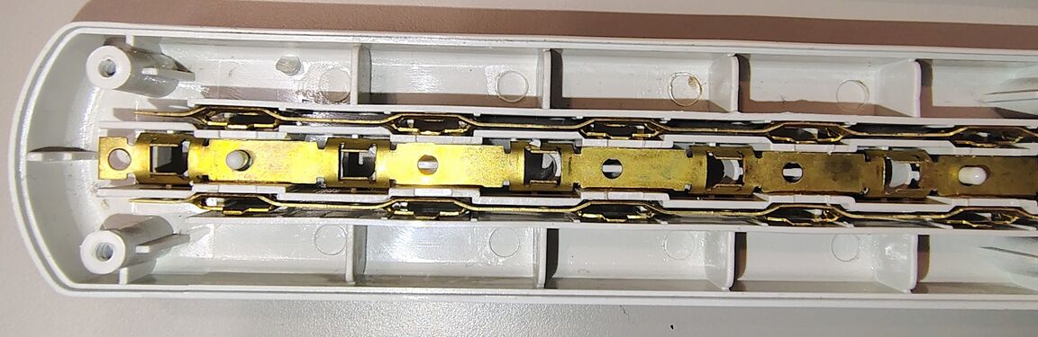 Outlet-end bus bars and outlet-contact assemblies.
 -
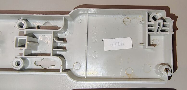 Control-section housing details.
 -
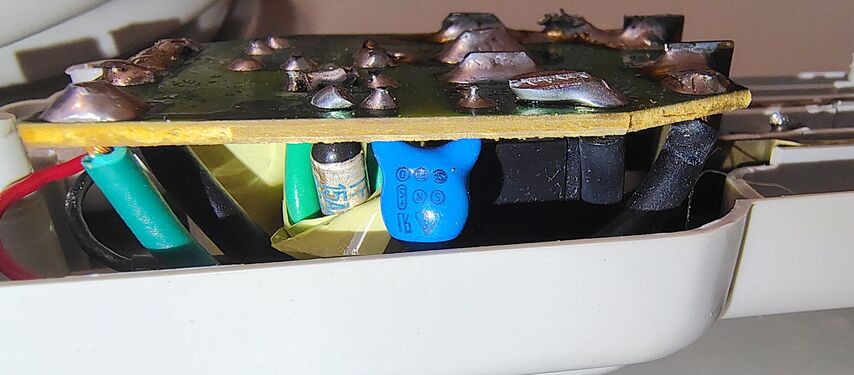 Side view of the surge-suppression circuit board.
 -
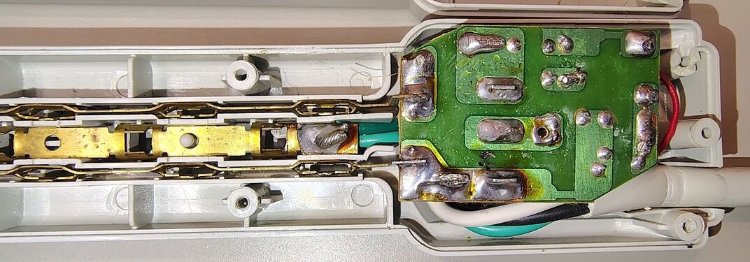 Cord-entry end showing wiring and bus-bar connections.
 -
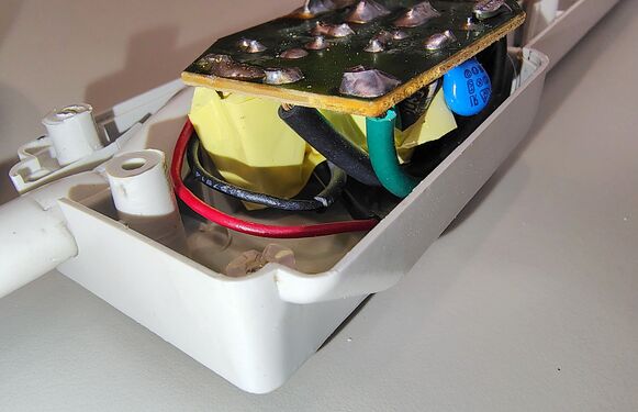 Surge-suppression circuit board and cord-entry wiring.
 -
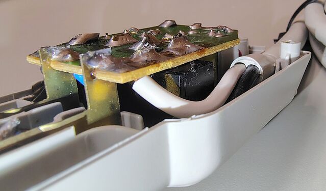 Alternate side view of the surge-suppression circuit board.
 -
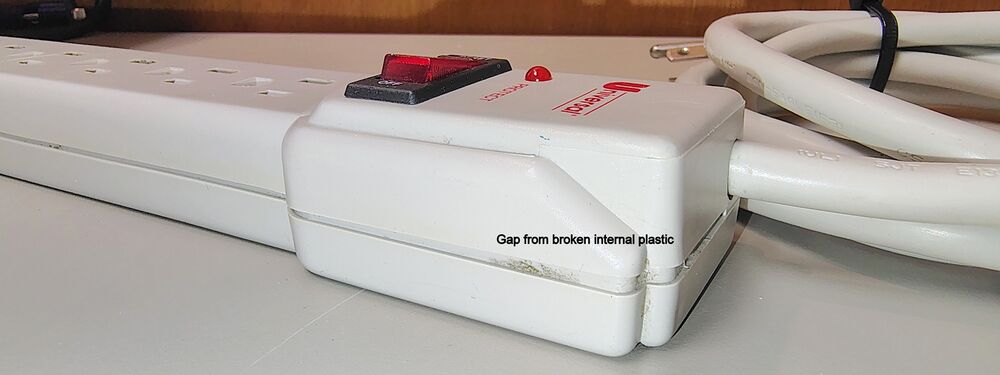 Housing separation caused by the broken internal screw post.


