Belkin SurgeMaster F9H710-06: Difference between revisions
No edit summary |
No edit summary |
||
| (One intermediate revision by the same user not shown) | |||
| Line 1: | Line 1: | ||
= Belkin SurgeMaster F9H710-06 = | = Belkin SurgeMaster F9H710-06 = | ||
[[File:surge-Belkin-SurgeMaster-F9H710-06-main_01.jpg|thumb|center|400px|Overall view of the Belkin SurgeMaster F9H710-06.]] | |||
== Overview == | == Overview == | ||
| Line 6: | Line 8: | ||
The model was marketed as part of Belkin's SurgeMaster product family and was intended for protecting computers, peripherals, telecommunications equipment, and other consumer electronics from power surges. | The model was marketed as part of Belkin's SurgeMaster product family and was intended for protecting computers, peripherals, telecommunications equipment, and other consumer electronics from power surges. | ||
== Features == | == Features == | ||
| Line 39: | Line 17: | ||
* Non-illuminated rocker power switch | * Non-illuminated rocker power switch | ||
* Telephone-line surge protection | * Telephone-line surge protection | ||
* | * Removable cable-management bracket | ||
* Attached six-foot power cord | * Attached six-foot power cord | ||
| Line 53: | Line 31: | ||
* Maximum Connected Load: 1875 W | * Maximum Connected Load: 1875 W | ||
* TVSS Rating: 330 V | * TVSS Rating: 330 V | ||
* Weight: Approximately 1 lb 6.2 oz (630 g) | |||
* Cord Length: Approximately 6 ft (1.8 m) | * Cord Length: Approximately 6 ft (1.8 m) | ||
* Length: Approximately 14.25 in (36.2 cm) | * Length: Approximately 14.25 in (36.2 cm) | ||
* Width: | * Width: | ||
** Approximately 3.125 in (7.9 cm) | ** Approximately 3.125 in (7.9 cm) across the top surface | ||
** Approximately 2.25 in (5.7 cm) | ** Approximately 2.25 in (5.7 cm) across the base | ||
* Height: Approximately 1.75 in (4.4 cm) | * Height: Approximately 1.75 in (4.4 cm) | ||
* Cord Type: SJT | * Cord Type: SJT | ||
| Line 67: | Line 46: | ||
* UL File Number (Cord): E177638 | * UL File Number (Cord): E177638 | ||
* Country of Manufacture: China | * Country of Manufacture: China | ||
* Manufacturing Date: November 1, 2003 (per molded date wheel markings) | * Manufacturing Date: November 1, 2003 (per molded date-wheel markings) | ||
== Physical Description == | |||
The F9H710-06 incorporates sliding outlet covers on all seven outlets. These covers may be positioned to expose or conceal outlet openings when not in use, helping to reduce the accumulation of dust and debris. | |||
The documented example exhibited dirt accumulation within the cover recesses. Following cleaning, all outlet covers operated normally. | |||
Telephone-line protection is provided through modular input and output jacks located at one end of the enclosure. The documented example appears to utilize only the center conductor positions of the modular connectors, consistent with two-conductor telephone-line applications. | |||
A removable gray cable-management bracket is positioned above the telephone-line protection connectors. The bracket slides vertically within molded slots and may be removed or raised to install cables. | |||
When lowered, the bracket helps align both telephone and power cables so they exit from a common end of the surge protector, creating a more organized cable bundle. | |||
A UL certification hologram attached to the underside bears a "09/03" marking, consistent with production during 2003. | |||
== Mounting Notes == | |||
The underside incorporates only two wall-mounting slots, both positioned off the centerline of the enclosure. | |||
Combined with the rounded, boat-shaped bottom profile, this arrangement can result in reduced stability when mounted and may allow the surge protector to rock slightly during insertion or removal of plugs. | |||
== Operational Testing == | == Operational Testing == | ||
| Line 96: | Line 95: | ||
<gallery mode="packed" heights="250"> | <gallery mode="packed" heights="250"> | ||
File:surge-Belkin-SurgeMaster-F9H710-06-top_01.jpg|Outlet covers in the open position. | File:surge-Belkin-SurgeMaster-F9H710-06-top_01.jpg|Outlet covers in the open position. | ||
File:surge-Belkin-SurgeMaster-F9H710-06-top_02.jpg|Outlet covers in the closed position. | File:surge-Belkin-SurgeMaster-F9H710-06-top_02.jpg|Outlet covers in the closed position. | ||
| Line 117: | Line 115: | ||
File:surge-Belkin-SurgeMaster-F9H710-06-cable-belkinbranding_01.jpg|Belkin SurgeMaster branding on the power cord. | File:surge-Belkin-SurgeMaster-F9H710-06-cable-belkinbranding_01.jpg|Belkin SurgeMaster branding on the power cord. | ||
File:surge-Belkin-SurgeMaster-F9H710-06-cablemarkings_01.jpg|Power cord specifications and ratings. | File:surge-Belkin-SurgeMaster-F9H710-06-cablemarkings_01.jpg|Power cord specifications and ratings. | ||
File:surge-Belkin-SurgeMaster-F9H710-06-weight_01.jpg|Weight measurement of the documented example. | |||
</gallery> | </gallery> | ||
Latest revision as of 17:35, 16 September 2026
Belkin SurgeMaster F9H710-06

Overview
The Belkin SurgeMaster F9H710-06 is a seven-outlet surge protector featuring telephone-line protection, surge suppression, and an attached six-foot power cord.
The model was marketed as part of Belkin's SurgeMaster product family and was intended for protecting computers, peripherals, telecommunications equipment, and other consumer electronics from power surges.
Features
- Seven grounded AC outlets
- Sliding outlet covers on all seven outlets
- Protected-status indicator
- Grounded-status indicator
- Non-illuminated rocker power switch
- Telephone-line surge protection
- Removable cable-management bracket
- Attached six-foot power cord
Specifications
- Model: F9H710-06
- Product Family: SurgeMaster
- Outlets: 7
- Telephone Protection: RJ11 input/output
- Maximum Load: 15 A
- Voltage Rating: 125 VAC
- Frequency: 60 Hz
- Maximum Connected Load: 1875 W
- TVSS Rating: 330 V
- Weight: Approximately 1 lb 6.2 oz (630 g)
- Cord Length: Approximately 6 ft (1.8 m)
- Length: Approximately 14.25 in (36.2 cm)
- Width:
- Approximately 3.125 in (7.9 cm) across the top surface
- Approximately 2.25 in (5.7 cm) across the base
- Height: Approximately 1.75 in (4.4 cm)
- Cord Type: SJT
- Conductor Size: 14 AWG
- Conductors: 3
- Temperature Rating: 60°C
- Flame Rating: VW-1
- UL File Number (Product): E152555
- UL File Number (Cord): E177638
- Country of Manufacture: China
- Manufacturing Date: November 1, 2003 (per molded date-wheel markings)
Physical Description
The F9H710-06 incorporates sliding outlet covers on all seven outlets. These covers may be positioned to expose or conceal outlet openings when not in use, helping to reduce the accumulation of dust and debris.
The documented example exhibited dirt accumulation within the cover recesses. Following cleaning, all outlet covers operated normally.
Telephone-line protection is provided through modular input and output jacks located at one end of the enclosure. The documented example appears to utilize only the center conductor positions of the modular connectors, consistent with two-conductor telephone-line applications.
A removable gray cable-management bracket is positioned above the telephone-line protection connectors. The bracket slides vertically within molded slots and may be removed or raised to install cables.
When lowered, the bracket helps align both telephone and power cables so they exit from a common end of the surge protector, creating a more organized cable bundle.
A UL certification hologram attached to the underside bears a "09/03" marking, consistent with production during 2003.
Mounting Notes
The underside incorporates only two wall-mounting slots, both positioned off the centerline of the enclosure.
Combined with the rounded, boat-shaped bottom profile, this arrangement can result in reduced stability when mounted and may allow the surge protector to rock slightly during insertion or removal of plugs.
Operational Testing
The documented example remains operational.
Testing with a receptacle tester confirmed correct outlet wiring and proper grounding.
When energized, both status indicators illuminated. The green Protected indicator remained illuminated, indicating that surge-protection circuitry was still active. The amber Grounded indicator confirmed the presence of a proper equipment ground.
The rocker power switch itself is not illuminated.
-
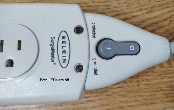 Protected and Grounded indicators unlit.
 -
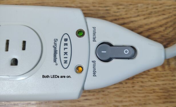 Protected and Grounded indicators illuminated.
 -
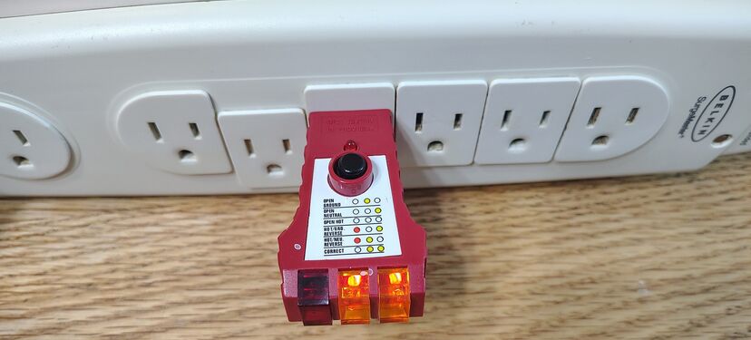 Outlet test confirming correct wiring and grounding.


Construction Notes
No disassembly was attempted.
The enclosure appears to utilize a snap-together construction with internal plastic retention clips. No externally accessible screws were observed. Opening the housing would likely require prying apart the enclosure along the seam, potentially damaging the case or visible exterior surfaces.
To preserve the condition of the documented example, disassembly was not attempted.
Product Gallery
-
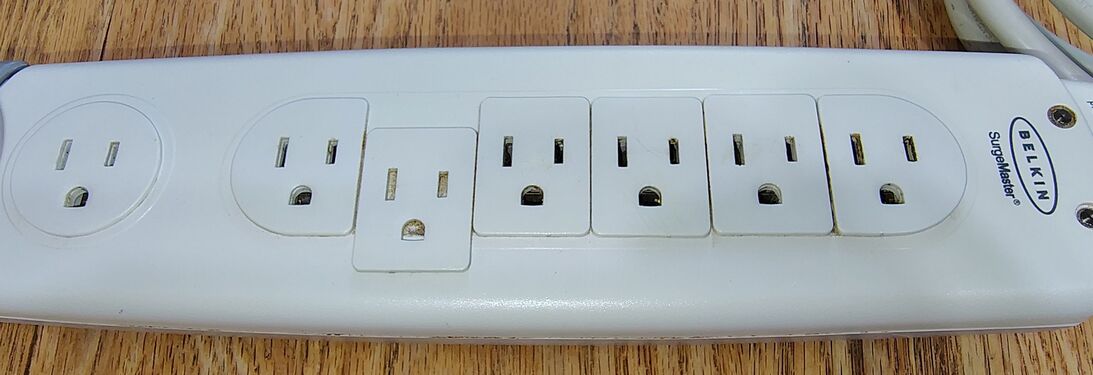 Outlet covers in the open position.
 -
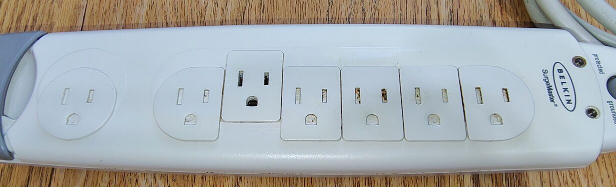 Outlet covers in the closed position.
 -
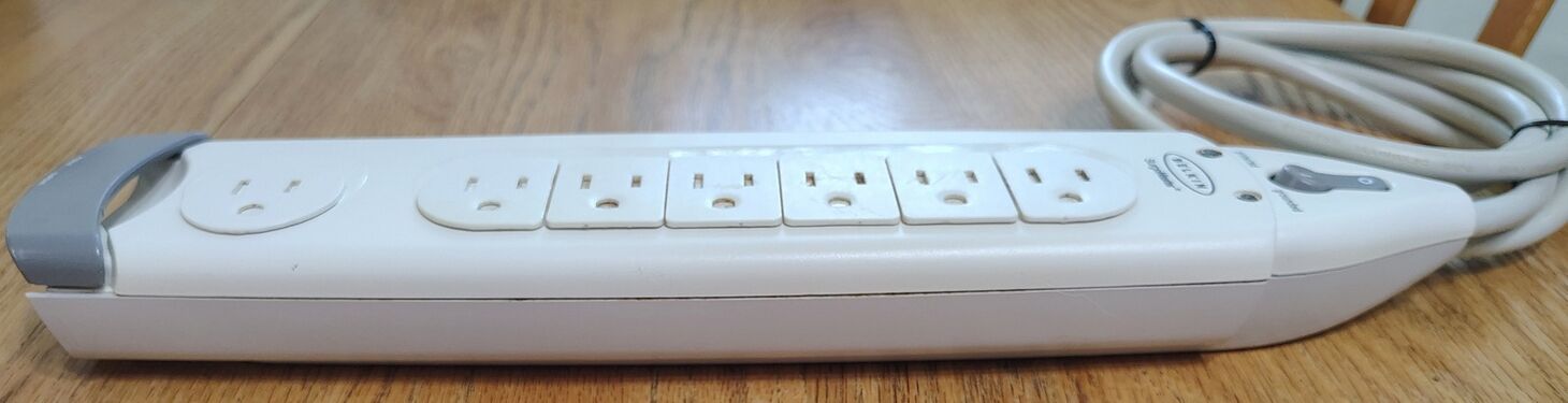 Right-side profile view.
 -
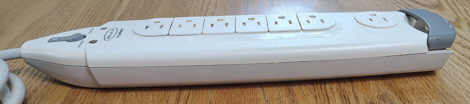 Left-side profile view.
 -
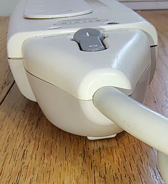 Power-cord entry and control section.
 -
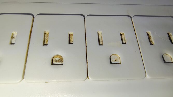 Sliding outlet covers in the closed position.
 -
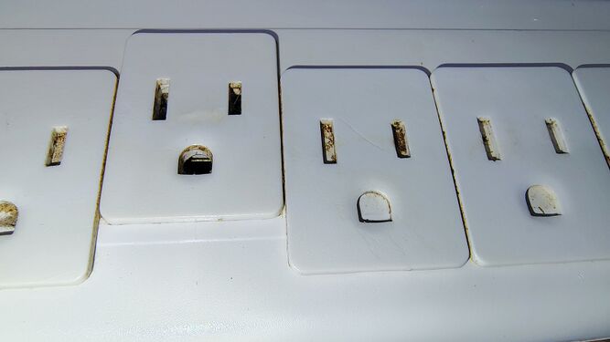 Outlet cover opened to expose the receptacle.
 -
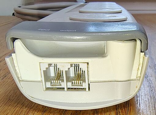 Telephone-line protection ports and cable-management bracket.
 -
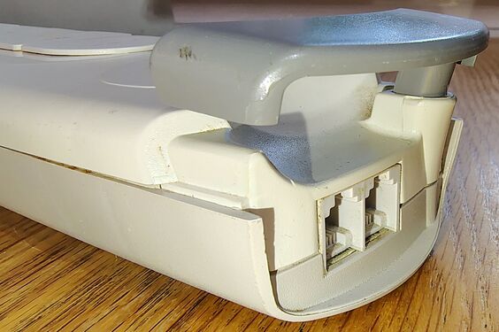 Cable-management bracket raised.
 -
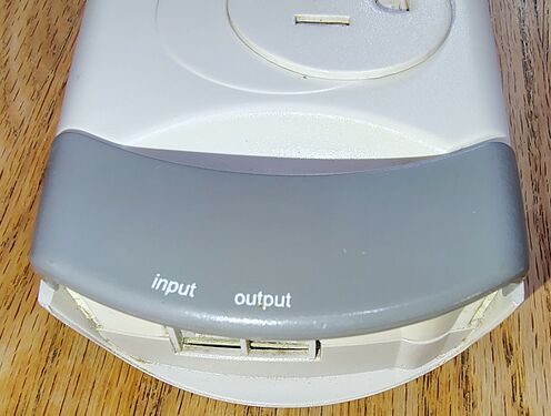 Telephone protection section and removable cable-management bracket.
 -
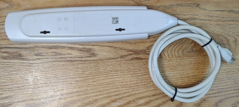 Underside view showing mounting provisions and product markings.
 -
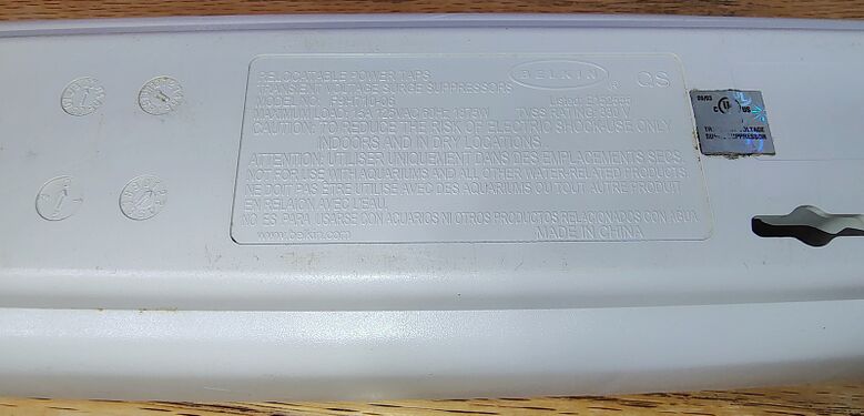 Product label, date codes, and mounting slot.
 -
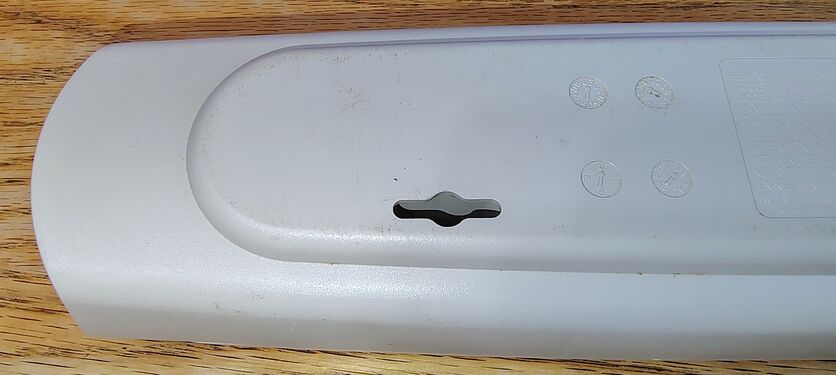 Telephone-protection end and wall-mounting slot.
 -
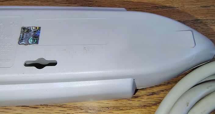 Power-cord entry end and certification markings.
 -
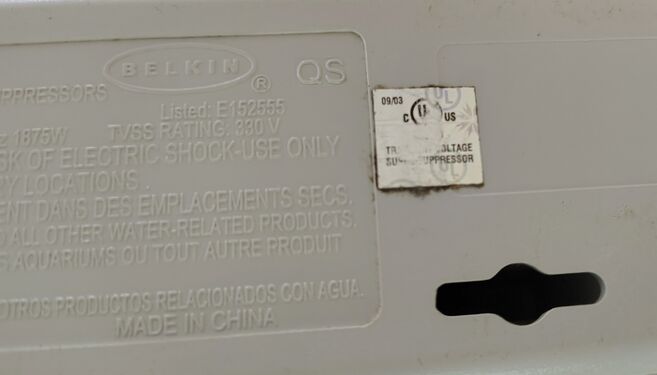 UL certification label and electrical ratings.
 -
 Underside production date wheels.
 -
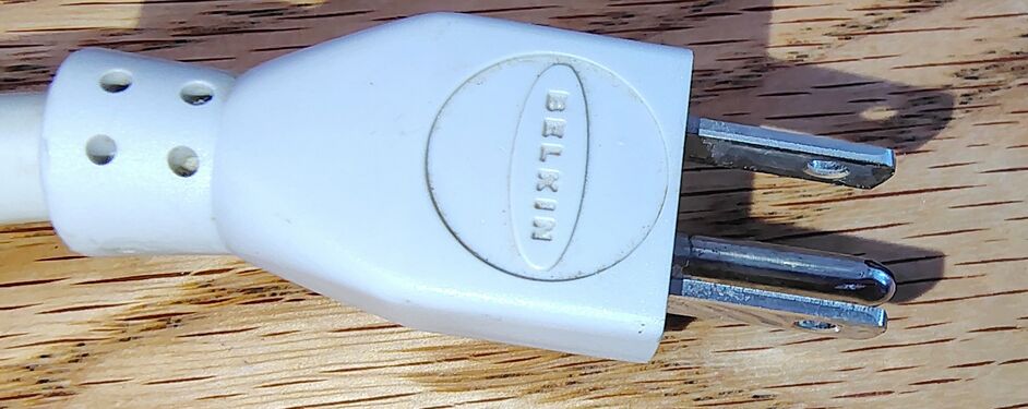 Belkin-branded grounding plug.
 -
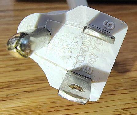 End view of the Belkin grounding plug.
 -
 Belkin SurgeMaster branding on the power cord.
 -
 Power cord specifications and ratings.
 -
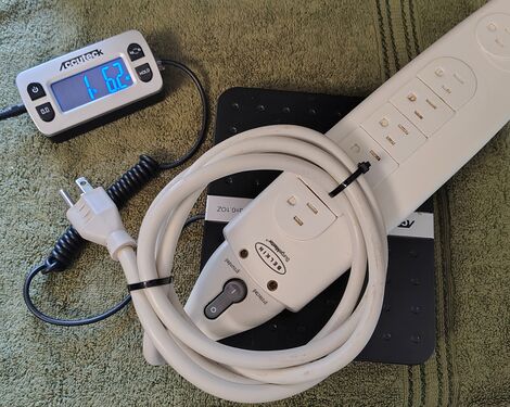 Weight measurement of the documented example.


Service History
The documented example remained in active service until 2026, when it was replaced by an Amazon Basics 270103-B surge protector.

At the time of removal from service, both the Protected and Grounded indicators remained illuminated, suggesting that surge protection and grounding status were still present.